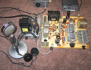
The receiver circuits are as follows: The first RF and mixer is a 6BE6 followed by a 6BA6 IF amplifier. The IN34 diode detector is switched to a single 6V6 AF amp in receive, see Relay RL1. The choke-coupled audio output is switched to a set of headphones via contacts on RL3. The receive crystal at 4340 KC. is switched to the 6AG7 oscillator in receive by additional contacts on RL1. The 6AG7 output feeds the mixer grid, pin #1, through contacts on RL2.
In transmit, the 3885 Kc. crystal is switched to the 6AG7 oscillator via RL1, and the 6V6 AF amplifier becomes a Heising modulator for the 6AG7 oscillator tube, note contacts on RL3. AF from a 12AX7 pre-amp., and
D-104 microphone, not shown, is through RL1 to the grid of the 6V6. The
6AG7 oscillator tube, now the PA output is switched to a Pi network through contacts on RL2. Note: the Pi network also feeds the first RF in receive and serves to peak signals at 3885 Kc., and/or acts as an antenna trimmer. So, when you peak the Pi network in receive you are ready to transmit.
As I remember, I could hear all the stations on the net, and the little transmitter put out about 4-watts of carrier. Later I made some improvements to the little rig to include a 12AX7 AF pre-amp for the
D-104. Then, one triode of the 12AX7 became first AF in receive which
allowed the 6V6 to drive a speaker instead of headphones. The addition of an AVC line improved the receiver performance, and I think that is where I left things!
I still have the little rig, but it actually aired on the PW net on my birthday, March 10th 2005.

